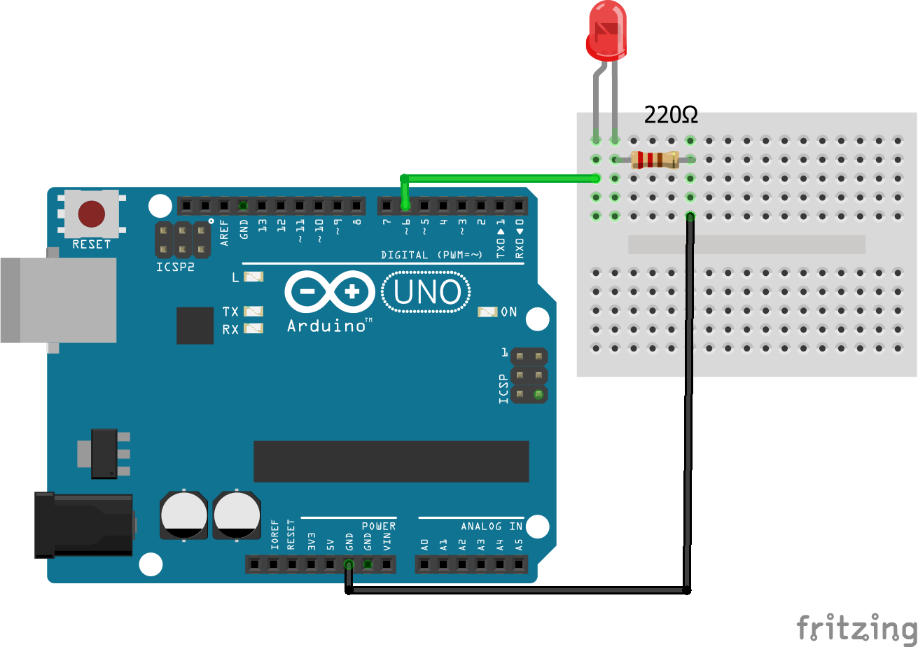

Like Arduino Mega, Arduino UNO, Arduino Nano, Lily Pad Arduino, and much more because as advance our projects are, Arduino keeps on updating its development board to keep teachers, students and other interested people updated as these boards are being used in. The internal resistor is built inside Arduino, we just need to set via Arduino code. Arduino makes a different type of development boards and each having different capabilities. We can use either an internal or external resistor. If otherwise, Arduino's pin state is HIGH. As the name suggests, these eight LEDs in a row successively light up and dim one after another, just like flowing water. If the button is pressed, Arduino's pin state is LOW. Flowing LED Lights With Arduino Uno R3: In this lesson, we will conduct a simple yet interesting experiment using LEDs to create flowing LED lights. Let us know your opinion about this short post with the starts you can find below, this gives us feedback about how we are doing. One button's pin is connected to GND, the other is connected to an Arduino's pin with a pull-up resistor.

#Arduino uno pinout code code

Thus, you have an ESP32 chip in the casing of an. But the best feature is that its 32 bits and dual core make it much more powerful. It has the 'face' of the Arduino Uno and is programmed with Arduino IDE. The Arduino IDE comes with an example LCD sketch which uses an Hitachi HD44780 compatible LCD. The Worlds Largest Arduino This is how I define this board that I’m introducing today, as it is basically a 'clone' of Arduino Uno.
#Arduino uno pinout code plus
Read the following interesting articles to keep learning about programming ESP8266 NodeMCU boards and Arduino IDE. If we each key as an independent button, it requires 16 Arduino pin for 16 keys plus GND pin.
#Arduino uno pinout code how to
Read Breadboard, Pinout and Dimmable LED with Pulse-Width Modulation (PWM), to know more about how to interact with pins in Arduino IDE, particularly the ESP8266 NodeMCU pinout section. Pinįor example, the following code initializes the GPIO 4 and 5 digital pins as input and output, respectively and the analog pin (A0) as input. Digital pins can be used as inputs or outputs, however the analog pin can only be used as an input. If we want to interact with a digital pin in Arduino IDE we have to remember the GPIO number (0.16), whereas for the analog pin the alias is used ( A0). We would really appreciate your support to our work and website if this is fine for you. This means if you click on the links and purchase the promoted item, we will receive a small affiliate commission at no extra cost to you, the price of the product is the same.


 0 kommentar(er)
